Version#
This quick start guide is for the following Viotel Wireless Triaxial Tiltmeter versions
Version: 2.1
Product Code: TILT-V2.1-INT
Hardware Type: 1147
Firmware version: 30220
Warning#
This guide intends to assist in the preferred mounting, operation and usage of Viotel’s Wireless
Triaxial Tiltmeter Node.
Please read and completely understand this user guide in order to make sure the safe and correct
use of the system as well as maintain the longevity of the device.
Protection provided by the equipment may be impaired if used in a manner contrary to this user
manual.
Changes or modifications not expressly approved by Viotel Limited could void the user’s authority to
operate the equipment.
This product must not be disposed of in the normal waste stream. It contains a battery pack and
electronic components and so should be recycled appropriately.
Theory of Operation#
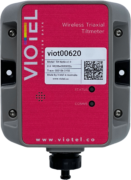
The Wireless Triaxial Tiltmeter is a low touch Internet of Things (IoT) device. It is designed to as
simple as possible to install and activate, set and forget. Data is retrieved from the device via our
cloud-based platform or via API to yours using the integrated LTE/CAT-M1 cellular communications.
The device also uses GPS for time synchronisation where comparison of events between nodes is
required.
The device sensor is always monitoring for events, and can be continuously monitoring, or set to a
triggered state and upload data in seconds. Remote configuration is possible to change the
acquisition and upload frequency.
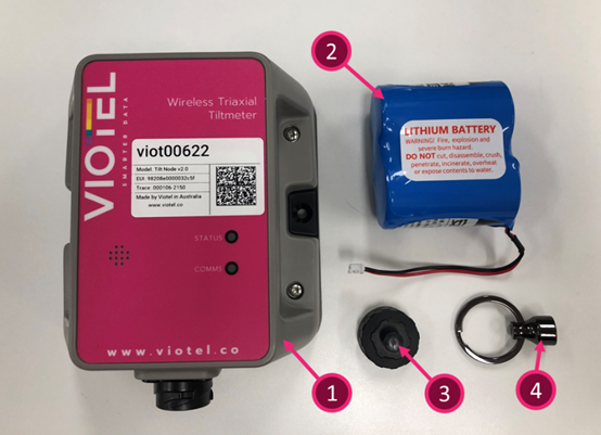
Parts List#
| Part |
Quantity |
Description |
Note |
| 1 |
1 |
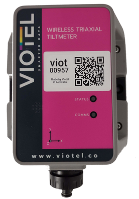
Wireless Triaxial Tiltmeter Node |
|
| 2 |
1 |
Battery pack (pre-installed into the device) |
|
| 3 |
1 |
Cap |
|
| 4 |
1 |
Magnet |
|
| 5 |
1 |
Optional Pole Mount Bracket |
|
Tools are not required for installation other than hand tools specific to your installation scenario.
The following tools are required for changing the batteries.
• T10 Torx Screwdriver
• Thin Needle Nose pliers
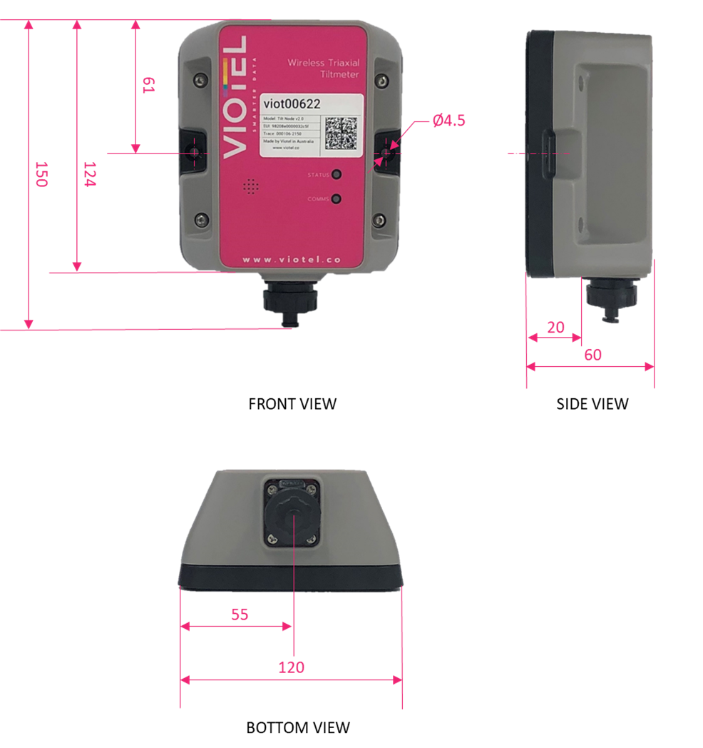
Dimensions#
Mounting Options#
Viotel’s Wireless Triaxial Tiltmeter Node comes with three primary mounting options. It is
recommended that a combination of two is used for optimal use.
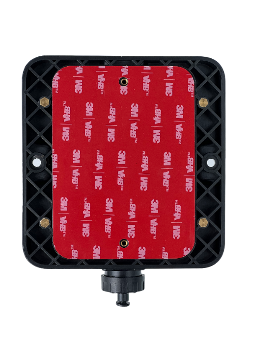
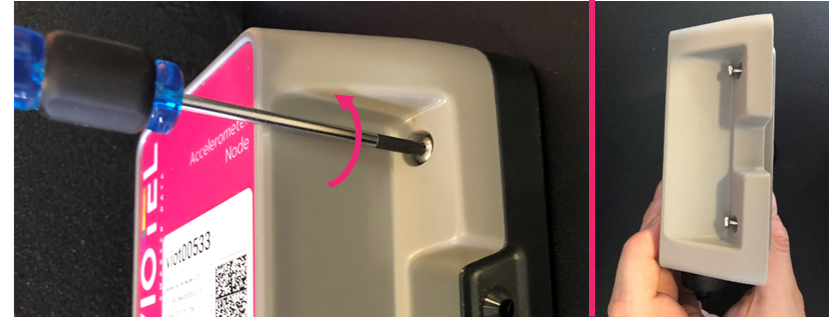
Two-Sided Adhesive
Clean and dry the mounting locations surface. Peel off the red plastic layer on the back of the node and firmly press it onto the required location. Keep the device and surface under this same pressure for approximately 20 minutes (to achieve 50% bond strength in room temperature).
Threaded M3 Holes
Threaded M3 Holes suitable for optional pole mount bracket or mounting to an enclosure.
Side Mounting holes
Side mounting points designed for M5 countersunk bolts or screws.
Magnet#
Refer Quick start guide on Magnets and how to use magnets
Orientation Description#
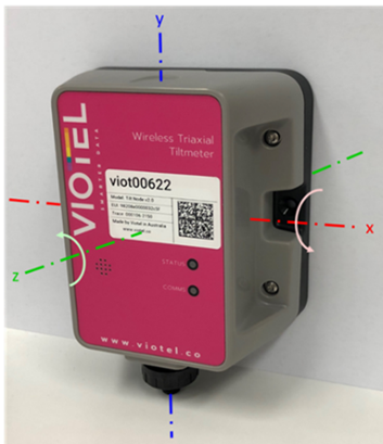
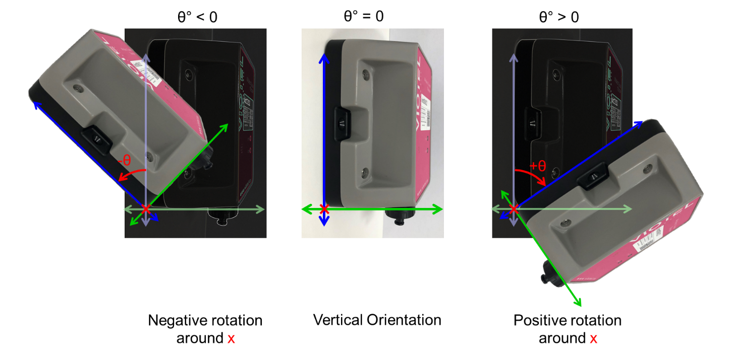
Rotation Around X (Rotation Around Wall Horizontal) (Pitch)
With the Viotel logo legible and node viewed from the left; a clockwise rotation around the horizontal axis (X Axis) will produce a positive angular change. Anticlockwise rotation around the horizontal axis (X Axis) will produce a negative angular change.
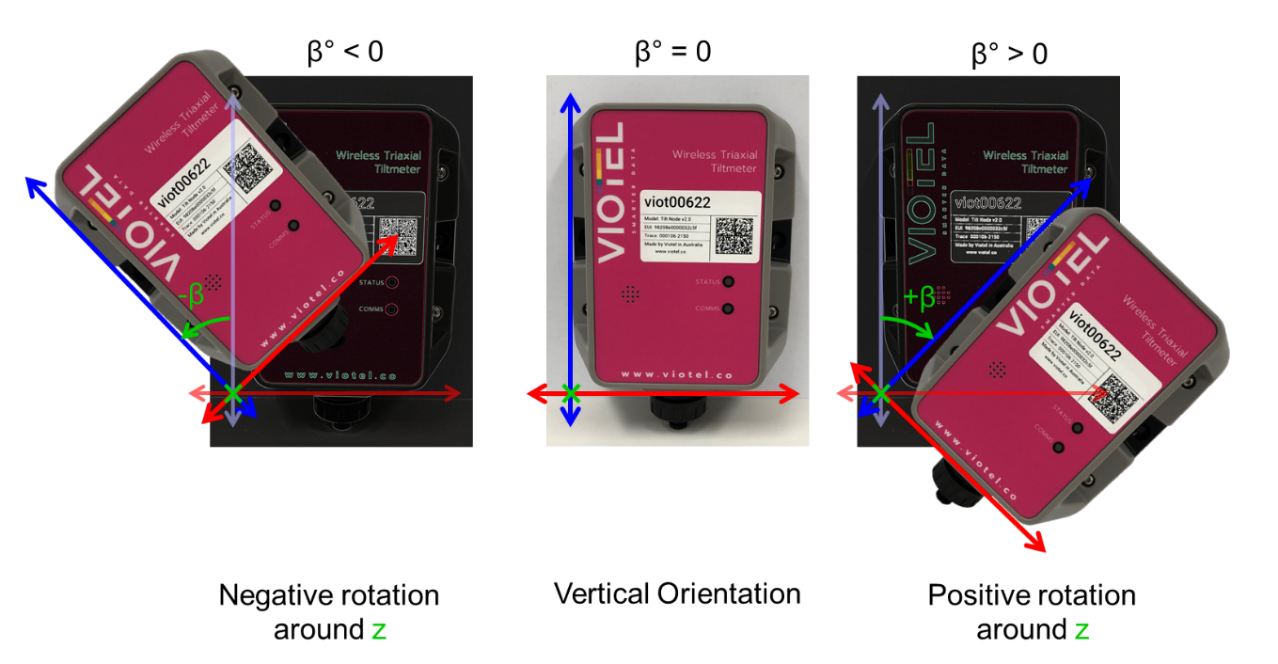
Rotation Around Z (Rotation Around Wall Perpendicular) (Roll)
With the Viotel logo legible and node viewed from the front, a clockwise rotation around the perpendicular axis (Z Axis) will produce a positive angular change. Anticlockwise rotation around the perpendicular axis (Z Axis) will produce a negative angular change.
Operation#
Refer Quick start guide on device status and how to use magnets to change the device status
Maintenance#
The product should not require any maintenance after installation. If the need to clean the product should arise, use only a damp cloth and mild detergent. Do not use any solvents as this may damage the enclosure.
Only service personnel authorised by the manufacturer may open the inner enclosure. No user serviceable parts are located inside.
Changing Batteries#
-
Please ensure the node is in Sleep state
-
Using the T10 Torx Screwdriver, unscrew until the 4 bolts on the front of the node’s enclosure are loose. Please note that the bolts are designed to remain in device section.
-
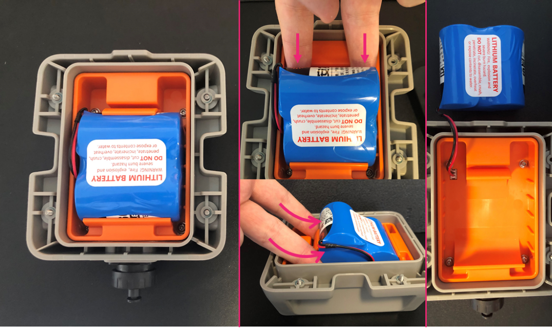
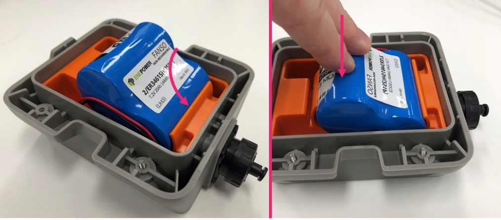
Flip over the top half of the enclosure making the battery pack is clearly visible. Position two fingers around the battery and firmly pull up; the battery should pop out of its holder. Ensure you do not pull or rip the red & black cables attaching the battery pack to the device.
-
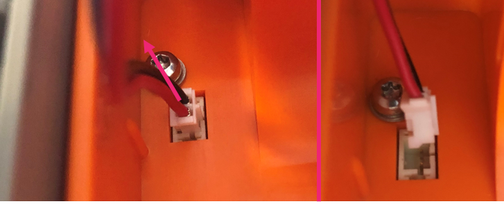
Gently pull out the exposed plug connecting the battery to the device. Please dispose of this used battery pack correctly based on legislative requirements.
-
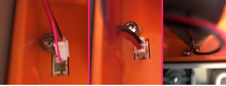
Gently push the new battery packs plug into the devices socket. A pair of thin needle nose pliers may be required to confirm it has been adequately plugged in.
-
Slide the battery pack into position and push firmly on the battery until it clicks into place.
-
Once the device is screwed back into the base, your node can be safely turned back to Awake state for use.

External power#
Please ensure the node is in Sleep state. It is strongly recommended that the battery be taken out of the enclosure. See changing batteries.
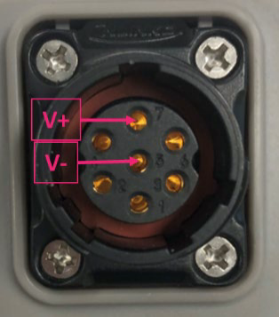
A seven-pin male CNLinko plug will be required to power externally.
PIN 5: Ground
PIN 7: Positive Voltage
POWER REQUIREMENTS: 7.5 VDC only.
Viewing and downloading Data#
Refer Viewing data in Quick Start Guide
If the device is in the field and is unable to upload data, the device is programmed to keep trying in decreasing increments to conserve battery. If after 4 days of attempting to upload, it will reboot. Data is stored on non-volatile memory; therefore, it is stored when rebooted and after power loss. Data is deleted from the device once successfully uploaded.
Firmware updates#
Viotel support may update the firmware of the device if required. The update happens over the air remotely and does not require physical access to the device. The Status LED will blink green four times every 1 second upon successful firmware update.
Further Support#
please contact us at support@viotel.co